<<<
etheli.com ArduVidRx
ArduVidRx Hardware
The ArduVidRx firmware may be run on various hardware configurations,
including the following ones. A Bluetooth module may be attached;
see the Bluetooth Modules for ArduVidRx
page for more information.
RC832 Receiver
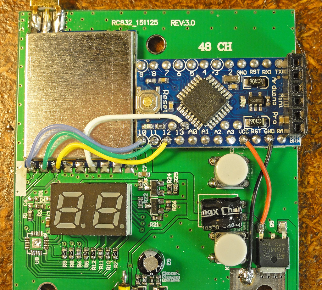

The "standard" ArduVidRx build consists of an RC832 video receiver modified with an Arduino
Pro Mini 328 (5V 16MHz) board. In the above photos, the one
on the left shows the minimum wiring required for ArduVidRx (see the min-wiring
diagram here). The one on the right shows the full wiring,
with connections for the 7-segment displays, buttons, and RSSI output
(see the full-wiring
diagram here).
The first step in the modifcation is to remove the U8 chip (below and
to the left of the display) so that the Arduino board is free to run
the module and display connections. It can be successfully
removed with a pencil-syle heat gun, but care needs to be taken
to avoid damaging the (plastic) display. (For the minimum-wiring
version of the modification, another option is to cut the traces to the
leftmost three connections on the RX5808 module.)
The Arduino board should be attached to the RC832 main board using
double-stick foam tape. See this
annotated case pic (rev3.0) for dimensions on the slot that needs
to be cut for the Arduino connector.
Note that the above photos are for the REV:3.0 version of the
RC832. For the REV:2.0 version of the RC832, see this wiring
photo, this annotated photo, and this
annotated case pic (rev2.0).
See here for a
gallery of BobD's build pics.
See here for a
gallery of earlier pics (showing wiring into an 8-conductor cable).
See here for a pic
showing a mount with case opening on the side.
(Special thanks to BobD for the pics and the work.)
The Arduino Pro Mini 328 (5V 16MHz) board may also be found here on
eBay.
Here is a source for the female headers: 2pcs 40Pin
2.54 mm Single Row Female Header
These headers have long pins on both sides making them good for use as
mating adapters:
20mm 2-sided 1x40-pin 2.54mm Breakaway Male Header - Double Sided
http://www.ebay.com/itm/141657908407
https://www.adafruit.com/products/400
A 5-volt FTDI
adapter is needed to load the firmware onto the Arduino board (see below).
Realacc RX5808 Pro Diversity Receiver
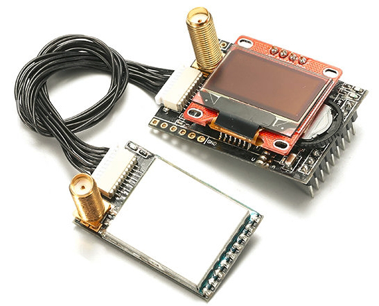

The Realacc RX5808 Pro Diversity is a receiver
designed to fit into Fatshark FPV goggles. Because it features
the pads for an FTDI connection, it is well suited to run the ArduVidRx
firmware. The combination of this module and the
SparkFun
Bluetooth Mate Silver provides the easiest build (in terms
of what soldering is required).
The diversity board (with the extra RX5808 module) and the display are
not used by the ArduVidRx firmware (though future enhancements could be
implemented to support them). The extra RX5808 module could also
be used to build another ArduVidRx receiver (see below).
A 6-pin header needs to be soldered onto the module (can use this Female
Header).
Note that with this header in place, the module may no long fit into
Fatshark goggles. If the module is powered via the VCC(+5V) and
GND pins on the Fatshark
connector,
a jumper to the VCC on the other connector is needed (to bypass a
diode). This allows the power to go out to the Bluetooth
module. See the right-side pic above. (Video and audio
signals can be tapped via the Fatshark connector.)
These headers have long pins on both sides making them good for use as
mating adapters:
20mm 2-sided 1x40-pin 2.54mm Breakaway Male Header - Double Sided
http://www.ebay.com/itm/141657908407
https://www.adafruit.com/products/400
A 5-volt FTDI
adapter is needed to load the ArduVidRx firmware onto the module (see below).
The Quanum HB5808 Diversity Receiver may also work as
an ArduVidRx receiver (although the pin spacing on the 6-pin connector
looks tighter).
Arduino Pro Mini + RX5808 module
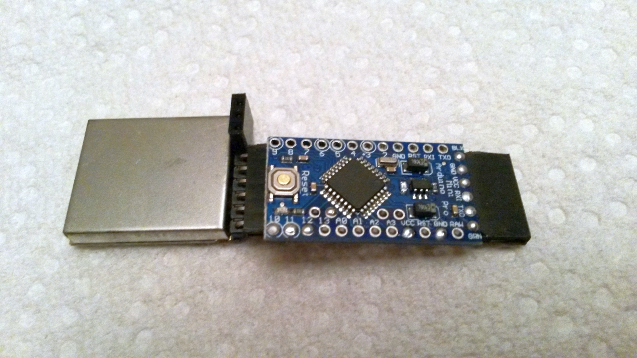
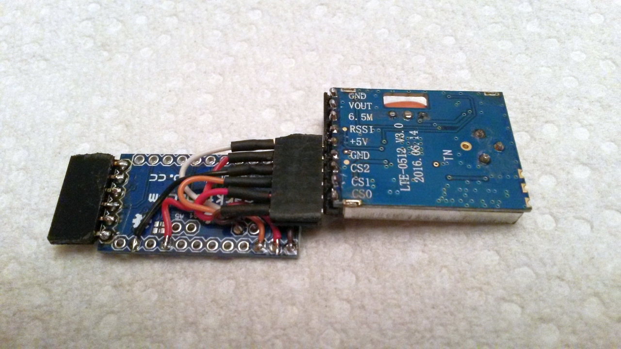
A stripped-down approach to creating an ArduVidRx receiver is to attach
an RX5808 module directly to an Arduino
Pro Mini 328 (5V 16MHz) board. Various wiring and connector
options are possible; the needed connections are shown here in the
min-wiring diagram. In the photos above, a 6-pin header is
soldered onto the FTDI-side of the Arduino board (can use this Female
Header),
and another 6-pin female header is wired into the necessary pins on the
Arduino. A right-angle 6-pin male header is soldered onto the
lower pins on the RX5808 module. A 3-pin female header is also
soldered on to provide access to the video and audio signals from the
module. See here
for an additional photo.
Here are a couple of sources for RX5808 modules:
FPV-5-8G-Wireless-Audio-Video-Receiving-Module-for-Boscam-for-RX5808
http://www.ebay.com/itm/112146512841
Boscam FPV 5.8G Wireless Audio Video Receiving Module RX5808
http://www.banggood.com/FPV-5_8G-Wireless-Audio-Video-Receiving-Module-RX5808-p-84775.html
On "older-style" versions of the RX5808 (like probably the one from
Banggood), the "SPI modification" needs to be done on the module -- see this page for information.
A 5-volt FTDI
adapter is needed to load the firmware onto the Arduino board (see below).
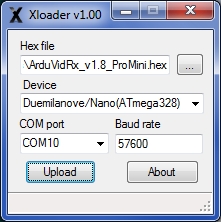
Loading ArduVidRx Firmware with XLoader
The ArduVidRx firmware can be loaded (flashed) to the receiver using the posted .hex file and the XLoader program. A 5-volt FTDI adapter is needed. Follow these steps for flashing:
- Download the ArduVidRx .hex file (right-click and select "Save As")
- Download "XLoader.zip" from the XLoader site
- Unzip "XLoader.zip" to a folder
- Attach the FTDI adapter to the 6-pin port on the ArduVidRx
receiver (check the pin labels to make sure the orientation is correct,
GND should go to GND, etc)
- Connect the other side of the FTDI adapter to the USB port on the computer
- Click on "XLoader.exe" to run the program
- Click on the '...' button, then find and select the ArduVidRx .hex file
- For 'Device', select "Duemilanove/Nano(ATmega328)"
- For 'COM port', select the port for the attached FTDI adapter
- For 'Baud rate', enter: 57600
- Click the 'Upload' button, and the firmware flashing should begin
- Wait for the firmware flashing to finish
(The ArduVidRx code can also be built and flashed using the Arduino IDE or the Eclipse C++ IDE for Arduino. The code is posted here on GitHub, or here as a zip archive.)
Click here to contact me
Back to etheli.com home page