<<<
etheli.com Home Page
 RotorHazard FPV Race Timer

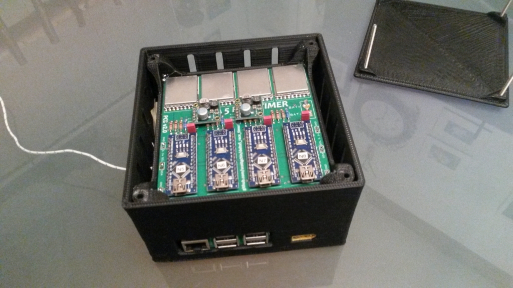
The RotorHazard FPV Race Timer
is an open-source multi-node timing system that uses the video signals
from FPV vehicles to determine when they cross the start/finish
line. The heart of the system is a Raspberry Pi, and each node
has a dedicated Arduino Nano and RX5808 module.
The Raspberry Pi runs the Raspbian OS (with desktop), and the
RotorHazard
system uses a server component written in Python. The
stand-alone-server version uses the 'Flask' library to serve up web pages to a computer
or hand-held device, via a network connection. An SQL database is
used to store settings (via the 'flask_sqlalchemy'
extension), and the 'gevent'
library is used to handle asynchronous events and threading. The
web pages that are served up use the Javascript 'Articulate.js'
library to generate voice prompts.
Check out RotorHazard on GitHub, here: https://github.com/RotorHazard/RotorHazard
See here for a gallery of pics of my
timer hardware.
Major Features
- Timing and event management on the same hardware
- Modern, mobile-friendly, and highly responsive user interface
- Manage pilots, heats, race classes, race formats, and tuning
profiles
- LED and audio support to indicate race staging, starts, and other
events
- Real-time statistics and race history
- Fine control of filtering and calibration allows indoor and
outdoor use, even in difficult multipathing environments
- Supports all frequencies in the 5.8GHz band
- Includes basic support for Team racing and most-laps-wins races
RotorHazard can be run with minimal hardware -- or even no hardware at
all!
To run RotorHazard on your PC, see the project docs
on Other Operating Systems.
See the USB
nodes doc for info on an easy-to-build single node version of
RotorHazard.
If no hardware nodes are connected, RotorHazard will operate using
simulated (mock) nodes. In this mode the web-GUI interface may be
explored and tested.
Discuss RotorHazard on Facebook: https://www.facebook.com/groups/rotorhazard
To report bugs or request features, please post a GitHub issue here.
The RotorHazard project is lead by Michael @ HazardCreative
and myself (ET).
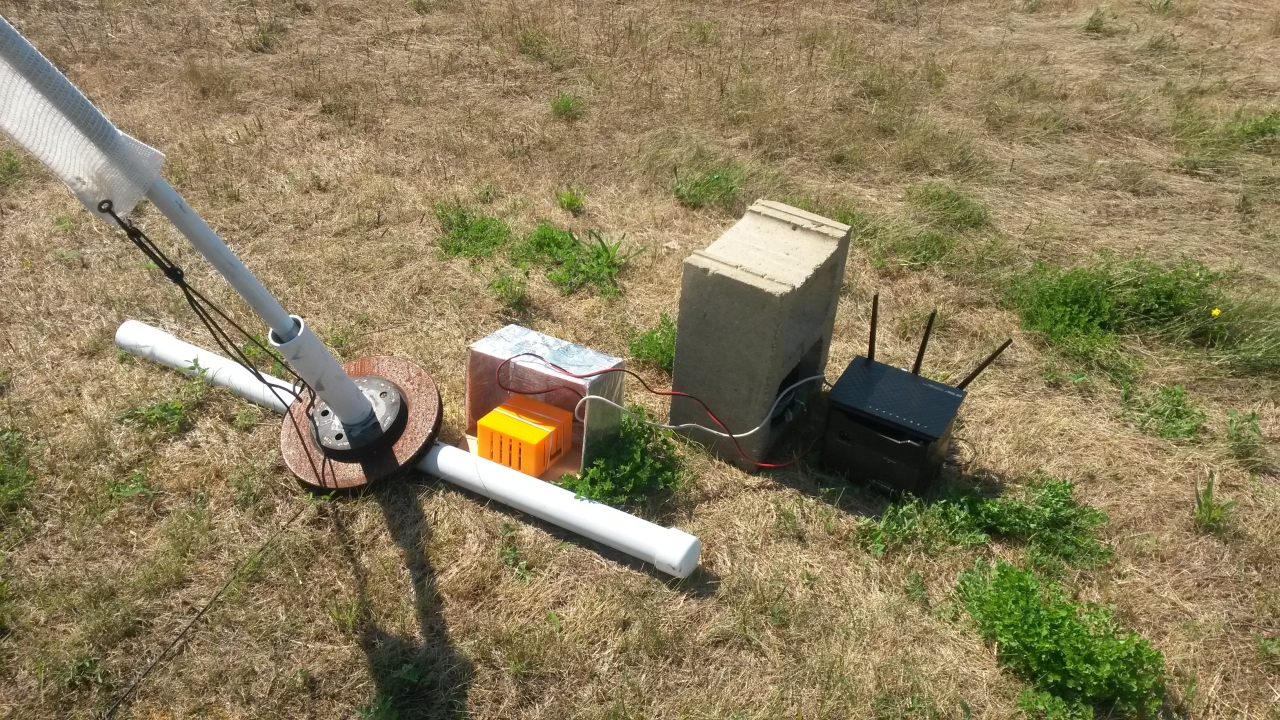
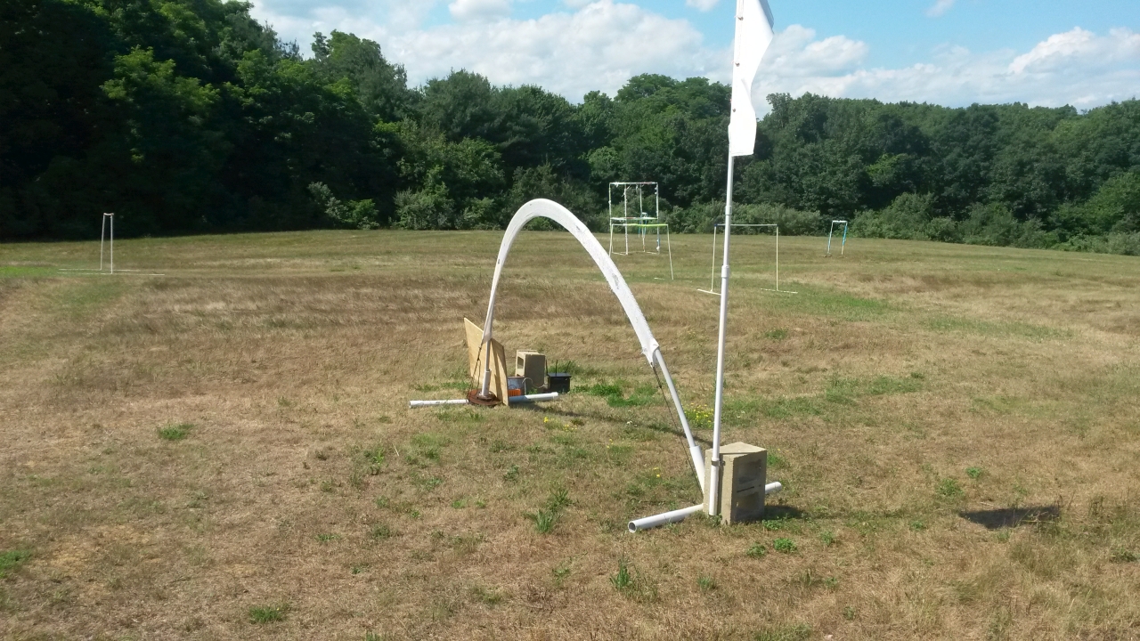
Here's a wireless setup for the race timer that I've found works well. The router is a bit to the
side and behind the (shielded) timer box to help prevent RF
interference. I have the router configured to use 5.2GHz (channel 40),
so it doesn't interfere with our video signals. When I tried running
the router on 2.4G I found that our RC transmitters raised major havoc
with the router data.
The power source is a fancy camping battery that one of the guys in
flying group kindly donated, but lipo batteries could work just as
well. The timer box is connected to the router via a short ethernet
cable. The link to the computer (showing the RotorHazard web/GUI
interface) is over wi-fi.
The router is an Asus RT-N66, running open source firmware (Tomato by
Shibby, K26RT-N / build5x-140-MultiWAN / Asus RT-N66u 64k / tomato-K26USB-1.28.RT-N5x-MIPSR2-140-AIO-64K.zip, local copy, how-to).
The router needs 19V input -- for my setup I'm able to use the
AC adapter, but if I needed to step the supply voltage up to 19V I
would use a Pololu regulator like the S18V20AHV.


Notes on building using the original Delta5 PCBs, as shown in the gallery of pics:
1. There are three cuts to PCB traces so that each of the Arduinos can
be individually powered, and disconnected from power by pulling the
nearby jumper. This makes it so that, if the jumper is pulled,
only the single Arduino receives power when updating its firmware using
its USB connector. The trace cuts are visible in this pic and this pic.
2. The +5V supply trace to each of the Arduinos was connected to VIN
(the input of the onboard 5V regulator), whereas they should be
connected to the actual 5V supply pads, so the red-wire jumpers make
that connection. Whether or not the +5V still connects to VIN
doesn't make much of a difference.
3. The black-wire jumpers connect ground on the PCBs to both ground
pads on the Arduinos instead of just one of them, but the board will
run the same either way.
4. In some of the pics there are two diodes and a resistor tied to the
I2C bus lines, but they are not necessary.
Part Links:
Arduino Nano V3.0 16M 5V ATmega328P module
https://www.ebay.com/sch/i.html?_nkw=Arduino+Nano+V3.0+16M+5V+ATmega328P
Boscam 5.8G Module RX5808
https://www.banggood.com/search/rx5808-module.html
https://www.ebay.com/sch/i.html?_nkw=rx5808+module
Pololu 5V, 2.5A Step-Down Voltage Regulator D24V25F5
https://www.pololu.com/product/2850
Pololu 3.3V, 2.5A Step-Down Voltage Regulator D24V25F3
https://www.pololu.com/product/2849
Click here to contact me
Back to etheli.com home page


